Summary
Magnetic Resonance Imaging
>General measurement principle
> Magnetic Resonance Velocimetry
> Magnetic Resonance Thermometry
> Technical Data
>List of sources
Magnetic Resonance Imaging (MRI) is a diagnostic method known from medicine. Among other things, this method enables two-and three-dimensional measurements of velocity and temperature fields, which is of great interest for engineering issues. In many cases, measurements are performed with water as fluid. However, measurements in other liquids and gases are also possible.
Although it is currently not possible to achieve the same resolution as in common measurement methods such as PIV or LDA, this method enables measurements in complex models without optical access and without additional particles or probes in the fluid flow. In addition, this method is capable of capturing millions of temperature and velocity data points within just a few hours. In combination with Rapid Prototyping or Additive Manufacturing methods, MRI enables new possibilities for the design and study of flow components. Where previously only numerical methods were available, MRI can be used to generate experimental data comparatively quickly and cost-effectively.
General measurement principle
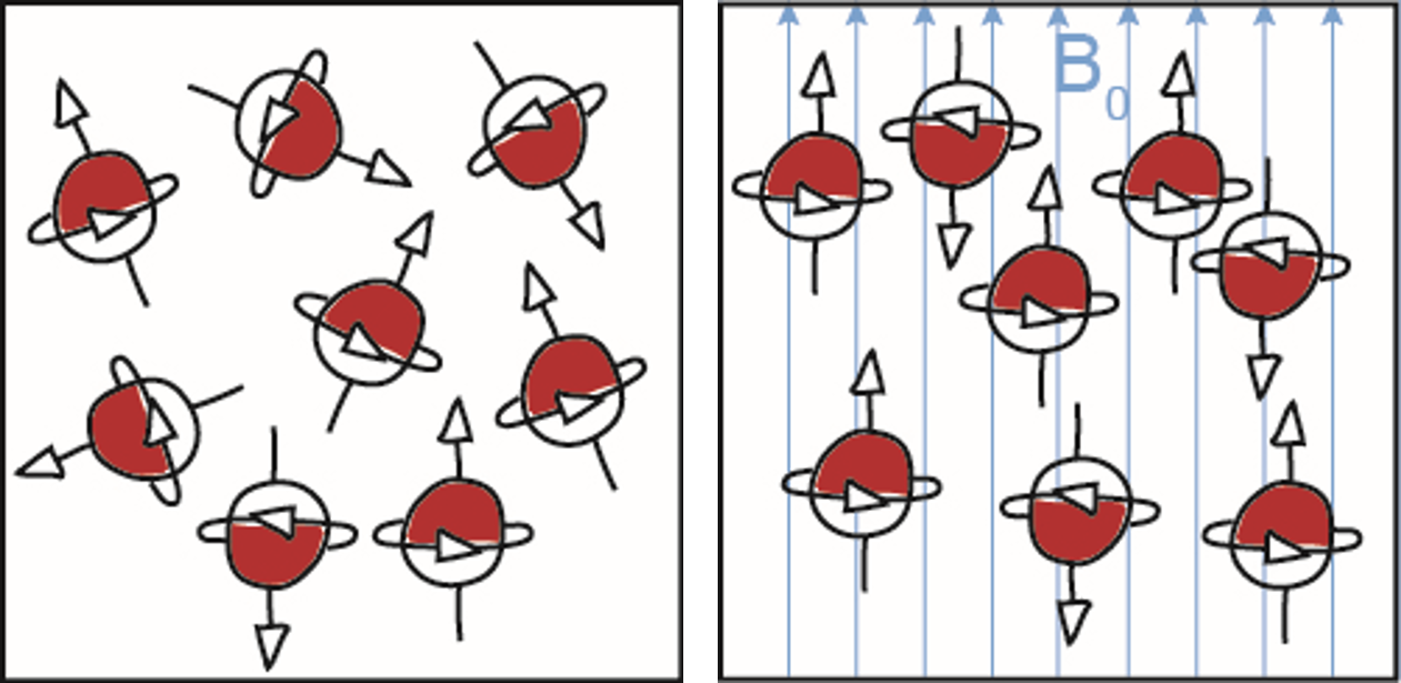
MRI is based on the behavior of non-zero nuclear spins in an external magnetic field. A commonly used nucleus is the hydrogen nucleus (1H) contained in water. However, many other other atomic nuclei such as 13C, 19F, 23Na and 129Xe can be used as well.
In an external magnetic field, the spins align along the magnetic field and precess with a characteristic frequency, which depends on the magnetic field strength of the outer magnetic field. Their magnetic moments build up a longitudinal magnetization, which can be tilted into the transverse plane by an electromagnetic pulse. Through the precession of the magnetization vector in the transverse plane, a voltage is induced in the receiver coils.
However, the signal generated in this way does not contain any information about the spatial distribution of the spins. In order to obtain this information, magnetic field gradients are used to generate a location- dependent magnetic field and therefore a spatial differentiation in form of frequencies. This spatial encoding is classified into slice selection, frequency encoding and phase encoding. The sequence of the switched gradients and excitation pulses is known as pulse sequence.
The frequency spectrum of the resulting signal is presented in the so-called k-space. From this the final image is obtained by a two- or three-dimensional Fourier Transform. Modern whole-body MRI Scanners allow to capture three-dimensional images with an edge length of several 100 mm and a resolution of less than 1 mm.
Magnetic Resonance Velocimetry
Magnetic Resonance Velocimetry (MRV) is commonly referred to as phase contrast MRI. The result of such a measurement is a complex image in which the phase angles contain information about the velocity distribution in the field of view.
As the underlying principle, the movement of the fluid particles along a magnetic field gradient induces a phase shift. The measurement sequences used for this purpose contain bipolar gradients: Two equal but opposite gradients are performed in a way that moving-particles result in a velocity-dependent phase shift. Within the same sequence a spatial encoding is performed. The resulting signal contains information about the velocity distribution inside the examined object.
This methods allows accurate and quick measurements of three-dimensional velocity vectors in fluid flows. In modern MRI scanners, the measurable range of flow velocities extends from a few centimetres to several meters per second.
Magnetic Resonance Thermometry
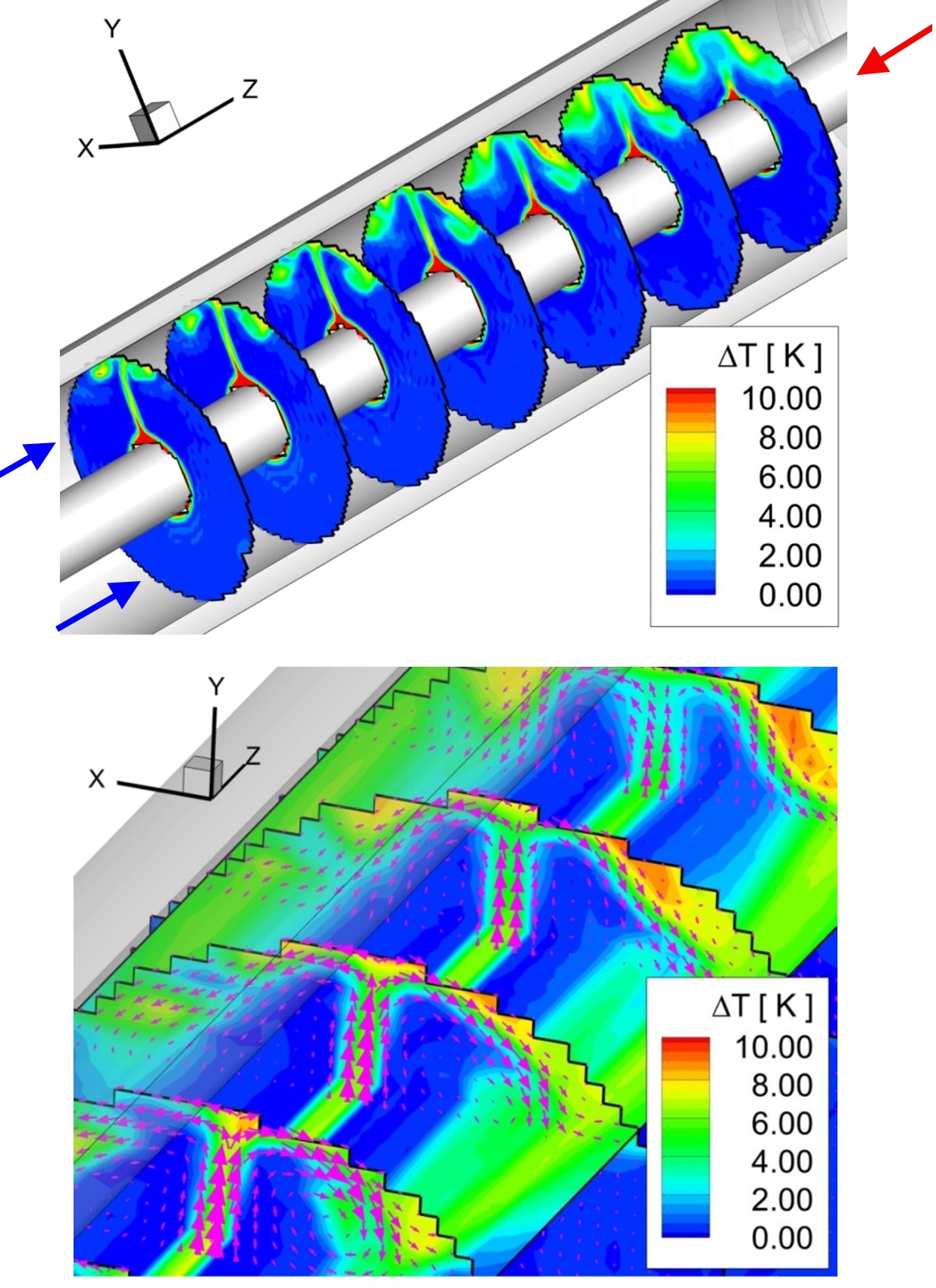
Several parameters in MRI are temperature-dependent. This includes:
- Proton resonance frequency
- Relaxation times
- Diffusion coefficient
- Susceptibility
This results in various possibilities for measuring temperature fields with MRI. The most common method of performing Magnetic Resonance Thermometry (MRT) is based on the temperature-dependent change in the proton resonance frequency of water. Like in MRV measurements, this method encodes the information about the temperature distribution in the phase of the resulting image. This procedure can be used to measure three-dimensional temperature fields with temperature differences less than 1 kelvin.
Technical Data
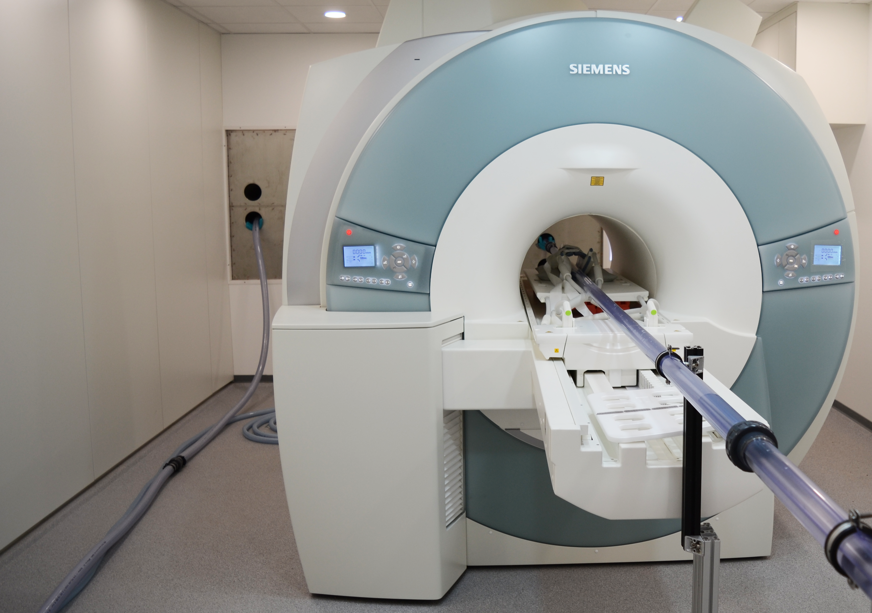
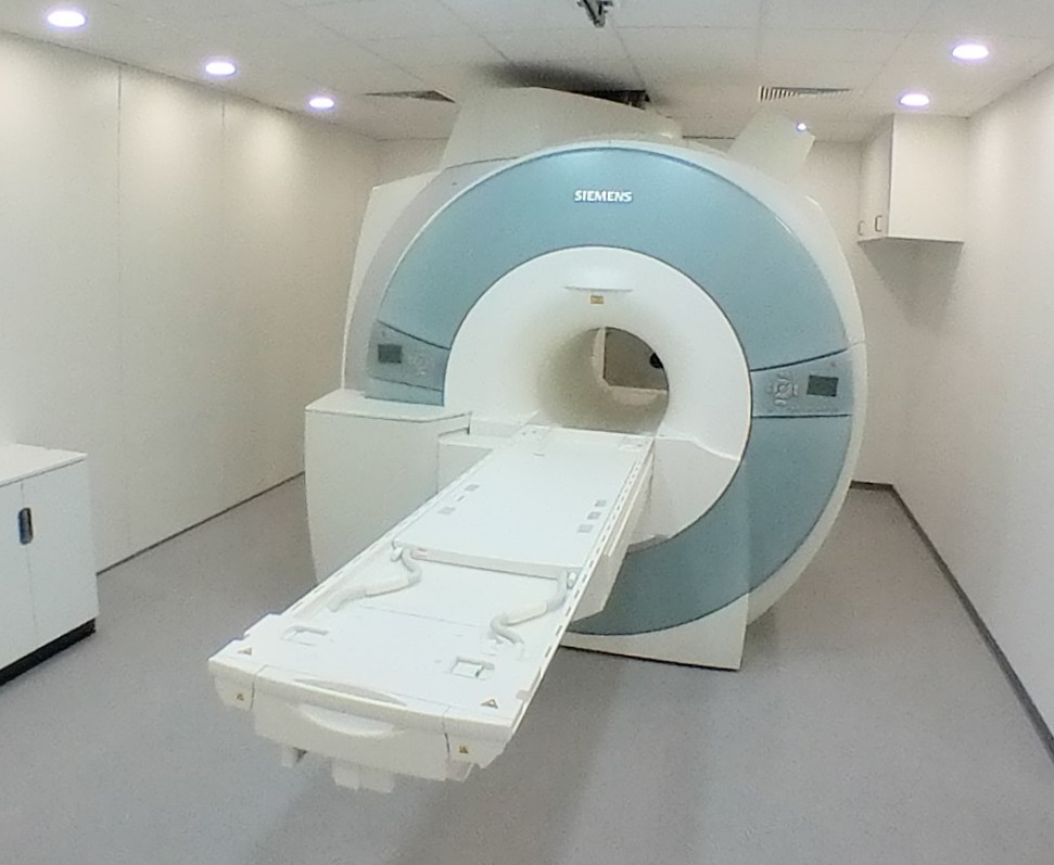
MAGNETOM Trio von Siemens
- 3 Tesla full body MRI Scanner with 600 mm inside diameter
- highest magnetic field homogeneity in this scanner class
- 40 mT/m or and 200 T/m/s magnetic field gradients
- variety of transmitting and receiving coils with up to 32 channels
- typical spatial resolution: 1 mm x 1 mm x 1 mm
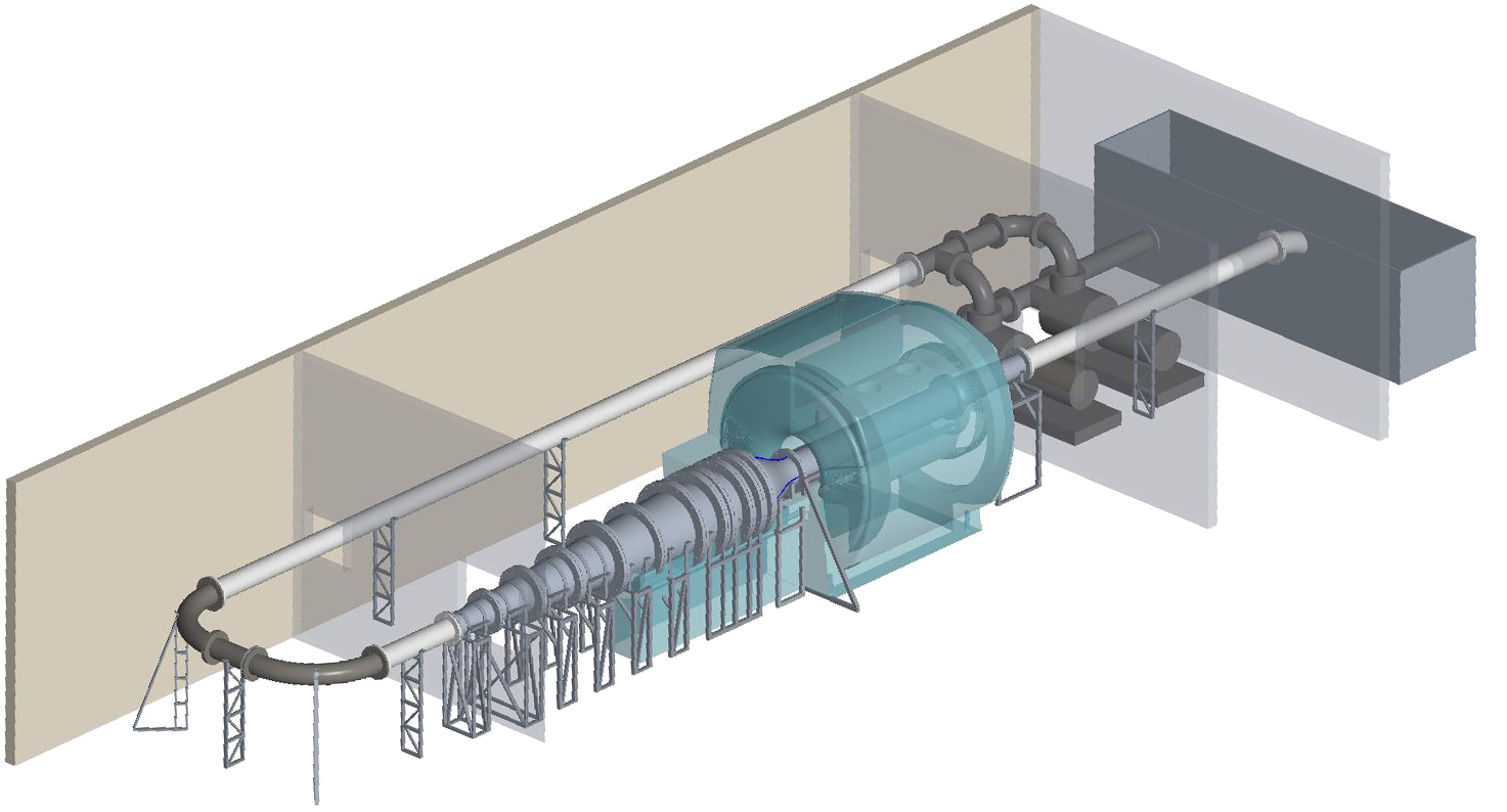
Flow supply system
The currently available system consists of several water tanks with a capacity of 1.0 m³ and several flow circuits with temperature and volume flow control. With this setup, Reynolds numbers between 1,000 and 100,000 can be achieved in the model being studied. The design of a more powerful flow system is shown on the right. This system is intended to realize fully turbulent flow conditions at a Reynolds number of up to 1,000,000.
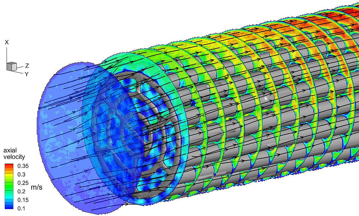
Bruschewski M, Freudenhammer D, Piro MHA, Tropea C and Grundmann S.
New insights into the flow inside CANDU fuel bundles using magnetic resonance velocimetry
Proc. Comp. Fluid Dyn. Nucl. React. Safety, Cambridge, USA (2016)
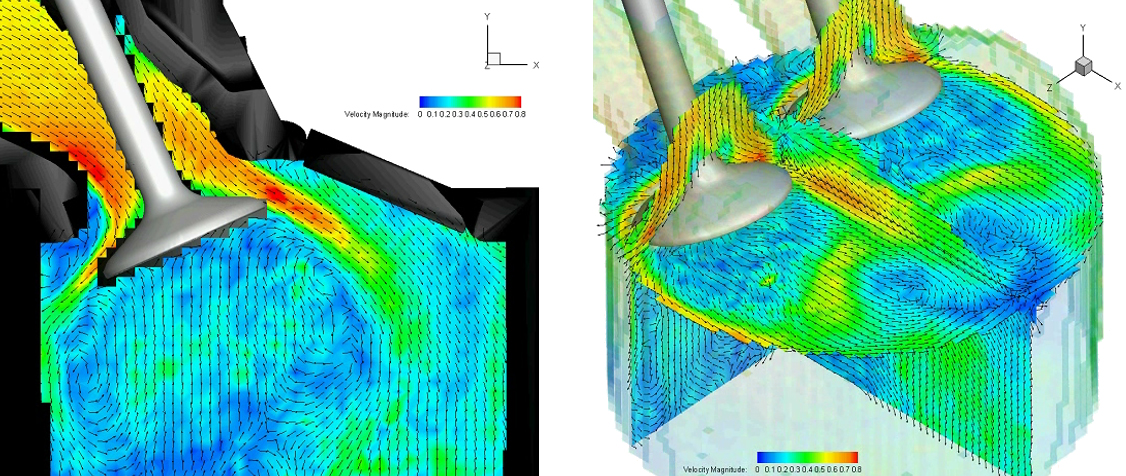
Freudenhammer D, Baum E, Peterson B, Böhm B, Jung B, Grundmann S.
Volumetric intake flow measurements of an IC engine using magnetic resonance velocimetry
Exp Fluids 2014; 55(5):1724
Buchenberg WB, Wassermann F, Grundmann S, Jung B, Simpson R.
Acquisition of 3D temperature distributions in fluid flow using proton resonance frequency thermometry
Magn Reson Med. 2016 ;76(1):145-55